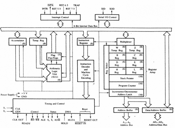
ARCHITECHTURE or FUNCTIONAL BLOCK DIAGRAM OF 8085
The functional block diagram or architechture of 8085 Microprocessor is very important as it gives the complete details about a Microprocessor. Fig. shows the Block diagram of a Microprocessor.
8085 Bus Structure: Address Bus:
- The address bus is a group of 16 lines generally identified as A0 to A15.
- The address bus is unidirectional: bits flow in one direction-from the MPU to peripheral devices.
- The MPU uses the address bus to perform the first function: identifying a peripheral or a memory location.
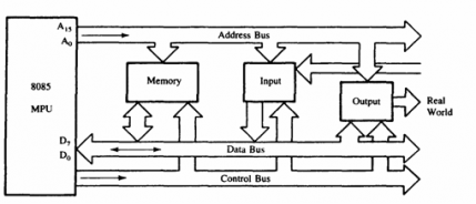
us:
- The data bus is a group of eight lines used for data flow.
- These lines are bi-directional - data flow in both directions between the MPU and memory and peripheral devices.
- The MPU uses the data bus to perform the second function: transferring binary information.
- The eight data lines enable the MPU to manipulate 8-bit data ranging from 00 to FF (28 = 256 numbers).
- The largest number that can appear on the data bus is 11111111.
- The control bus carries synchronization signals and providing timing signals.
- The MPU generates specific control signals for every operation it performs. These signals are used to identify a device type with which the MPU wants to communicate.
- The 8085 have six general-purpose registers to store 8-bit data during program execution.
- These registers are identified as B, C, D, E, H, and L.
- They can be combined as register pairs-BC, DE, and HL-to perform some 16-bit operations.
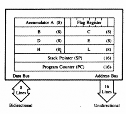
- The accumulator is an 8-bit register that is part of the arithmetic/logic unit (ALU).
- This register is used to store 8-bit data and to perform arithmetic and logical operations.
- The result of an operation is stored in the accumulator.
- The ALU includes five flip-flops that are set or reset according to the result of an operation.
- The microprocessor uses the flags for testing the data conditions.
- They are Zero (Z), Carry (CY), Sign (S), Parity (P), and Auxiliary Carry (AC) flags. The most commonly used flags are Sign, Zero, and Carry.

1.Sign Flag (S):
After execution of any arithmetic and logical operation, if D7 of the result is 1, the sign flag is set. Otherwise it is reset. D7 is reserved for indicating the sign; the remaining is the magnitude of number. If D7 is 1, the number will be viewed as negative number. If D7 is 0, the number will beviewed as positive number.
2..Zero Flag (z):
If the result of arithmetic and logical operation is zero, then zero flag is set otherwise it is reset.
3.Auxiliary Carry Flag (AC):If D3 generates any carry when doing any arithmetic and logical operation, this flag is set. Otherwise it is reset.
4.Parity Flag (P):
If the result of arithmetic and logical operation contains even number of 1's then this flag will be set and if it is odd number of 1's it will be reset.
5.Carry Flag (CY):
If any arithmetic and logical operation result any carry then carry flag is set otherwise it is reset.
Arithmetic and Logic Unit (ALU):
Temporary Register: It is used to hold the data during the arithmetic and logical operations. Instruction Register: When an instruction is fetched from the memory, it is loaded in the instruction register. Instruction Decoder: It gets the instruction from the instruction register and decodes the instruction. It identifies the instruction to be performed. Serial I/O Control: It has two control signals named SID and SOD for serial data transmission. Interrupt Control Unit:
- It is used to perform the arithmetic operations like addition, subtraction, multiplication, division, increment and decrement and logical operations like AND, OR and EX-OR.
- It receives the data from accumulator and registers.
- According to the result it set or reset the flags.
- This 16-bit register sequencing the execution of instructions.
- It is a memory pointer. Memory locations have 16-bit addresses, and that is why this is a 16-bit register.
- The function of the program counter is to point to the memory address of the next instruction to be executed.
- When an opcode is being fetched, the program counter is incremented by one to point to the next memory location.
- The stack pointer is also a 16-bit register used as a memory pointer.
- It points to a memory location in R/W memory, called the stack.
- The beginning of the stack is defined by loading a 16-bit address in the stack pointer (register).
Temporary Register: It is used to hold the data during the arithmetic and logical operations. Instruction Register: When an instruction is fetched from the memory, it is loaded in the instruction register. Instruction Decoder: It gets the instruction from the instruction register and decodes the instruction. It identifies the instruction to be performed. Serial I/O Control: It has two control signals named SID and SOD for serial data transmission. Interrupt Control Unit:
- It receives hardware interrupt signals and sends an acknowledgement for receiving the interrupt signal.
- It is used to perform the arithmetic operations like addition, subtraction, multiplication, division, increment and decrement and logical operations like AND, OR and EX-OR.
- It receives the data from accumulator and registers.
- According to the result it set or reset the flags.
- This 16-bit register sequencing the execution of instructions.
- It is a memory pointer. Memory locations have 16-bit addresses, and that is why this is a 16-bit register.
- The function of the program counter is to point to the memory address of the next instruction to be executed.
- When an opcode is being fetched, the program counter is incremented by one to point to the next memory location.
- The stack pointer is also a 16-bit register used as a memory pointer.
- It points to a memory location in R/W memory, called the stack.
- The beginning of the stack is defined by loading a 16-bit address in the stack pointer (register).
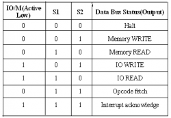
- It has three control signals ALE, RD (Active low) and WR (Active low) and three status signals IO/M(Active low), S0 and S1.
- ALE is used for provide control signal to synchronize the components of microprocessor and timing for instruction to perform the operation.
- RD (Active low) and WR (Active low) are used to indicate whether the operation is reading the data from memory or writing the data into memory respectively.
- IO/M(Active low) is used to indicate whether the operation is belongs to the memory or peripherals.
- If,
Interrupt Control Unit:
- It receives hardware interrupt signals and sends an acknowledgement for receiving the interrupt signal.
